


Galaxy S3 Motherboard Replacement

Send this link via e-mail
|
Tweet |
|


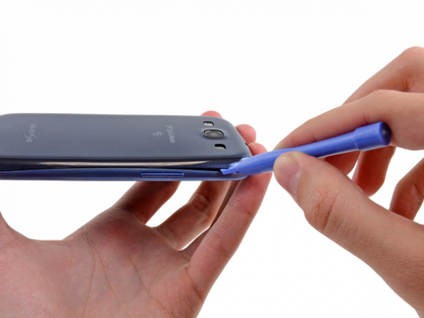
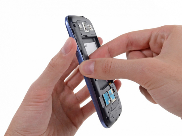
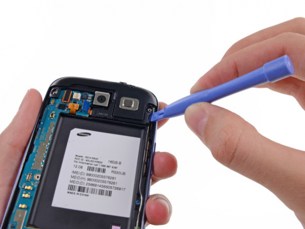
Step 1 - Rear Case
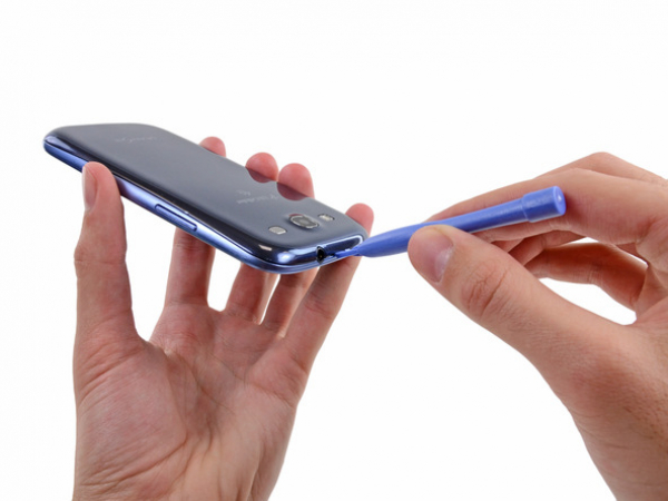
It is recommended to use a plastic tool for opening the rear case in the next four steps in order to avoid damaging of the clips along the perimeter of the case.
On the top part of the unit, in the notch where the rear case and the rest of the phone connect, insert the plastic or any other slim tool.
Carefully twist the tool until the clips disconnect.


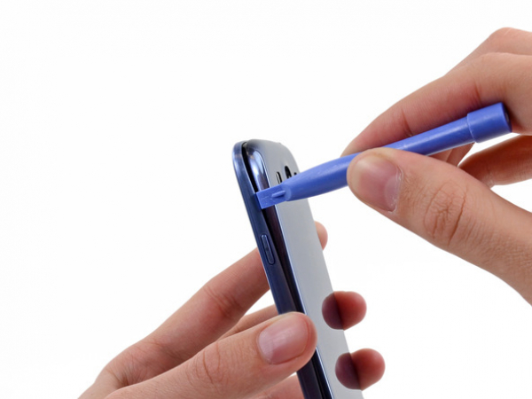
Step 2
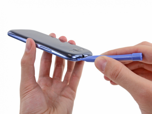
Once again insert the tool from the left top side and continue with gentle twisting of the tool so the the gap can widen up.


Step 3
Continue to move the plastic opening tool around the perimeter of the top left corner, gently prying up along the rear case.


Step 4
Lever the top right side first, and repeat the same action with the down right side of the case.
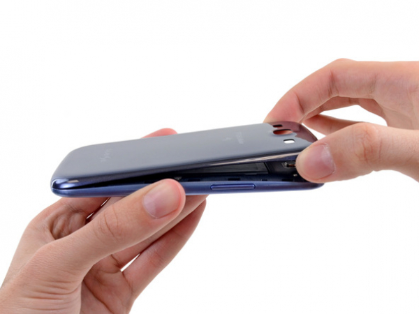


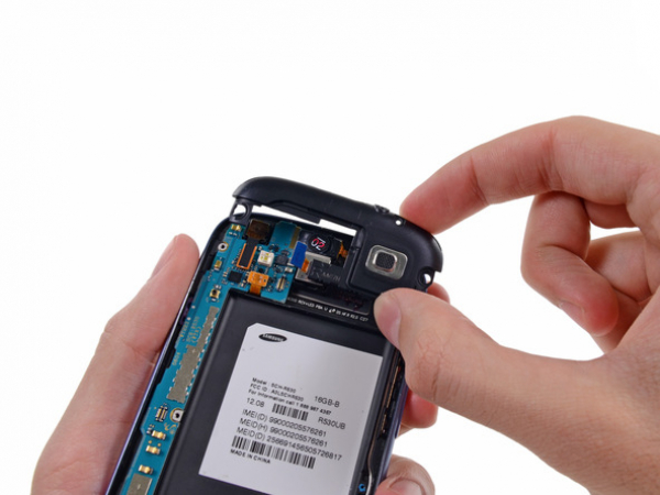
Step 5
Lift up the rear part of the case and remove it from the device.
If some clips are still holding the case down at the bottom, you should carefully peel it up in order to separate it from the rest of the phone.
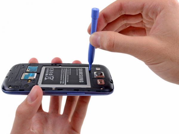


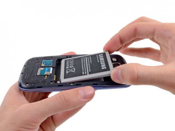
Step 6 - Battery
Back to top
For this step you may not need to use any tools, but it is still recommended.
Insert the opening tool into the small notch above the battery and lever it carefully.


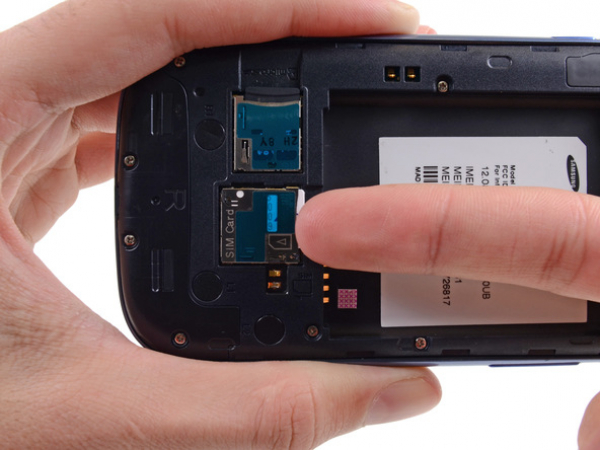


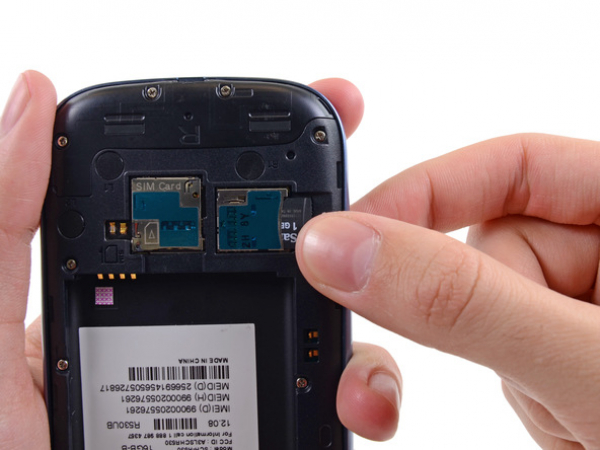
Step 8 - SIM Card
Back to top
Push the SIM card with your fingernail deeper into the slot.
The moment you hear the click, release the card. It will come out of its slot instantly.
For the reassambly process, place the SIM card back into its slot and push it until it clicks again. This way you will be certain it is in the right position.
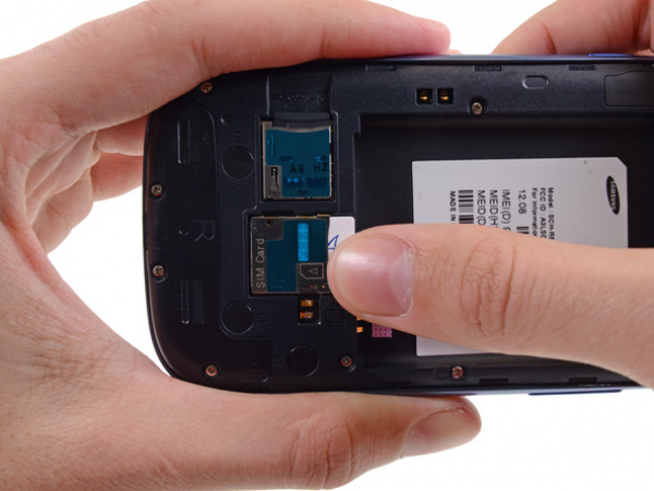


Step 10 - MicroSD Card
Back to top
Note: The procedure of microSD removal is the same as the one with SIM card.
Push the microSD card with your fingernail deeper into the slot. The moment you hear the click, release the microSD card. It will come out of its slot instantly.
For the reassembly process, place the microSD card back into its slot and push it until it clicks again. This way you will be certain it is in the right position.
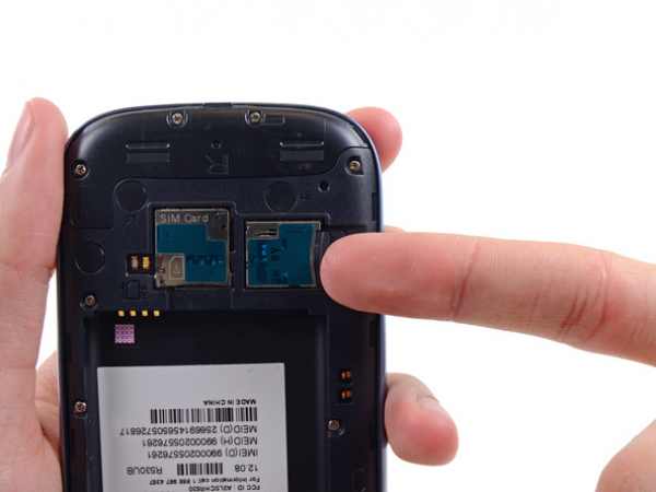
Step 11
With your thumb slide the microSD card out of the slot.
Take the microSD card out of the phone.
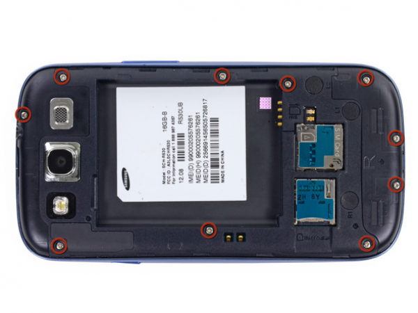
Step 12 - Plastic Mid-frame
Back to top
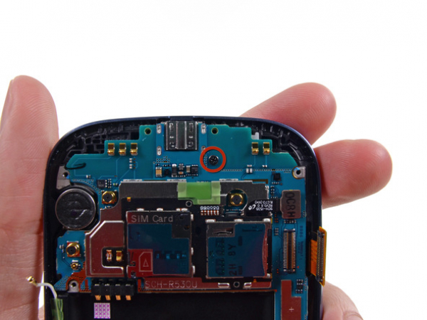
Ten 4.0 mm Phillips #0 screws that secure the mid-frame to the front panel assembly should be removed carefully.


Step 13
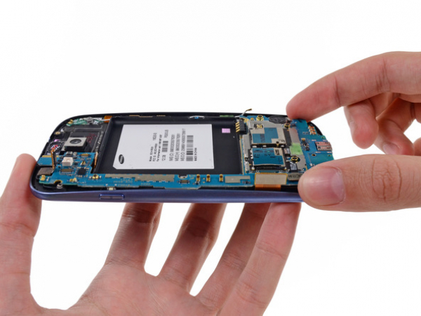
With two fingers take the left side of the plastic mid-frame and remove it from the phone gently.
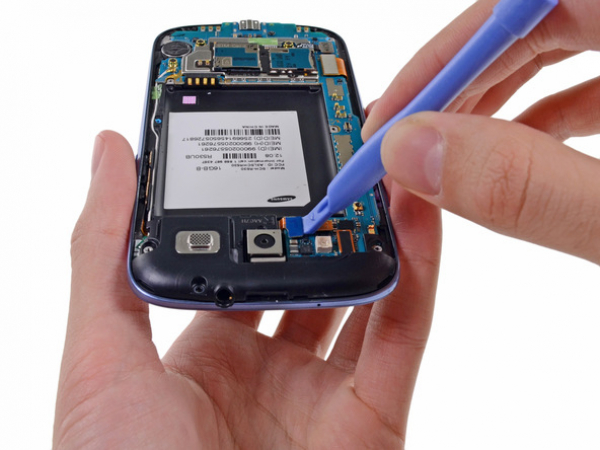


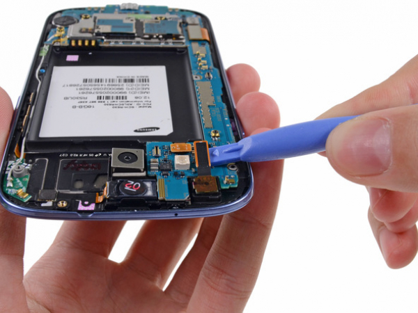
Step 14 - Headphone Jack/Speaker Assembly
Back to top
Carefully lever the rear-facing camera connector from its motherboard socket by using the plastic opening tool.
Pay attention: You should lever the connector and not the socket. Otherwise you might damage the motherboard.


Step 15
To remove the headphone jack/speaker assembly, insert the opening tool from the front side of the speaker portion.
Lever the headphone jack/speaker assembly gently from the front assembly.
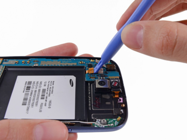
Step 17 - Motherboard Assembly
Back to top
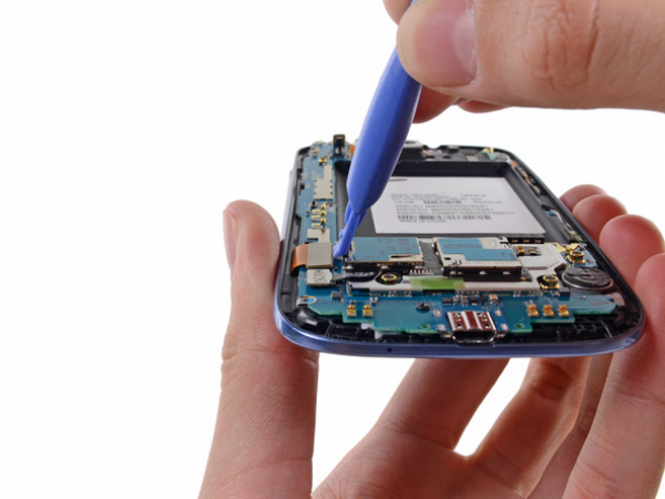
Lever the front-facing camera connector from its socket on the motherboard with the opening tool.
Do not try to remove the front-facing camera just yet. The cable of the camera is still routed under the motherboard assembly to the ambient light sensor.


Step 18
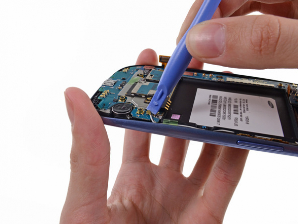
Carefully lever the connector of the digitizer cable to disconnect it from its socket on the motherboard.


Step 20
Lever the Wi-Fi antenna cable connector from its socket on the motherboard.
Gently remove the cable from the motherboard.