


Galaxy S3 Front Panel Replacement

Send this link via e-mail
|
Tweet |
|
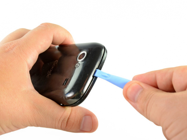
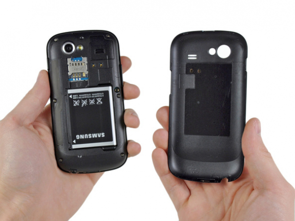
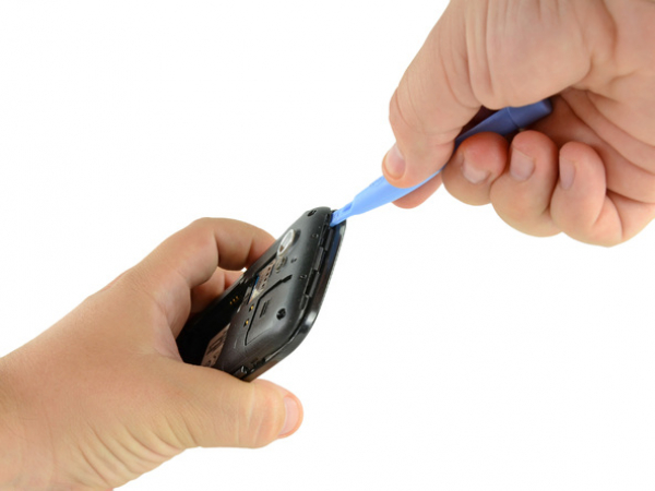
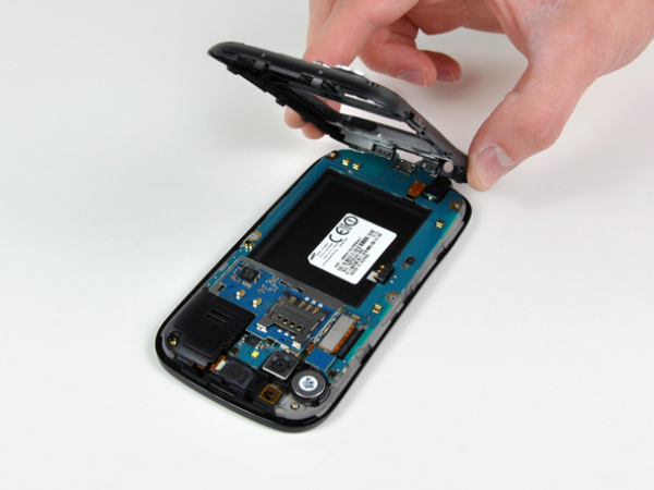
Step 1 - Rear Panel
Carefully insert a plastic opening tool between the rear panel and the inner rear frame near the rear-facing camera.
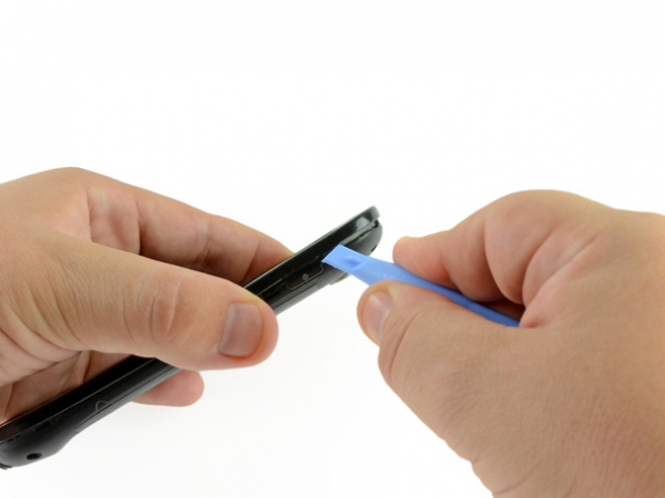
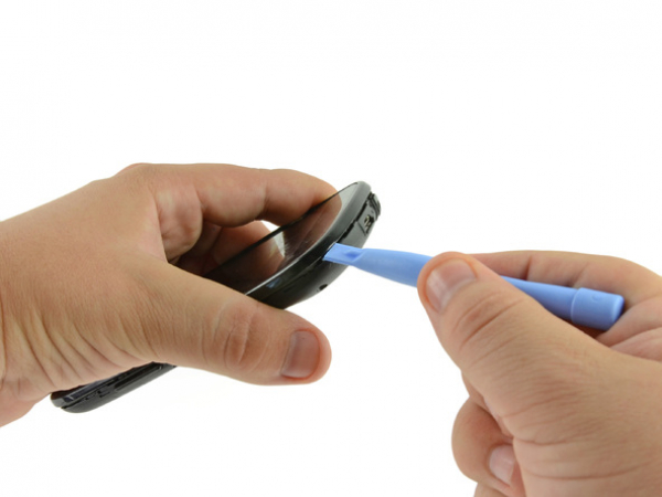
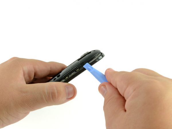
Pry up the rear case around the edges of the Nexus S using your plastic opening tool.
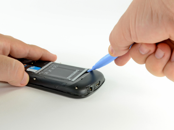
Step 3 - Battery
Back to top
Lift the battery from the end closest to the headphone jack using the edge of a plastic opening tool.
Now the battery can be removed from the Nexus S.
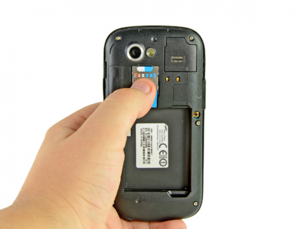
Step 4 - SIM Card
Back to top
Slide the SIM card downwards from the SIM card slot using your thumb.
Remove the SIM card.
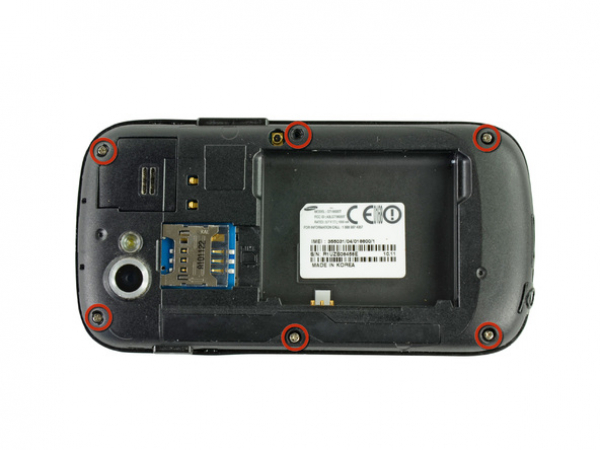
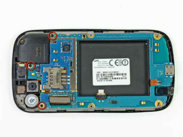
Step 5 - Rear Inner Frame
Back to top
Six Phillips screws securing the rear inner frame to the inner case need to be removed.
Step 6
Carefully insert the flat edge of a plastic opening tool in between the rear inner frame and the top left corner of the Nexus S.
Pry the opening tool upwards to pop the top right corner from the clips securing it to the inner assembly.
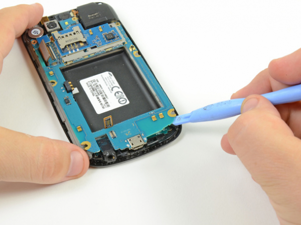
Step 7
Insert the plastic opening tool to the right of the power button.
In order to release the clips on the right side, you need to slide the plastic opening tool downwards along the edges of the Nexus S.


Step 8
Release the bottom clips located near the bottom of the Nexus S in the same way as previously described.
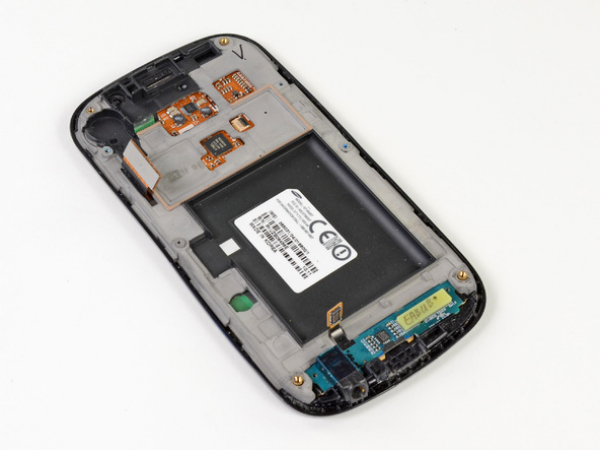
Step 9
In order to release the final clip securing the rear inner frame to the inner assembly, you need to insert and pry the plastic opening tool.
Step 11 - Motherboard
Back to top
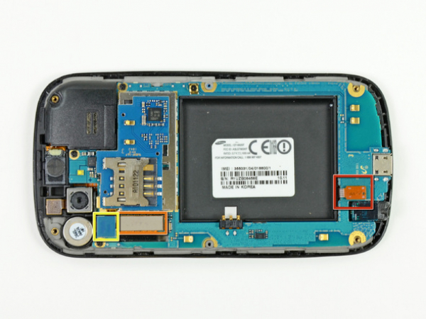
Disconnect the following cables from the corresponding sockets on the motherboard:
Headphone jack cable
Digitizer cable connector
Camera/SIM board connector
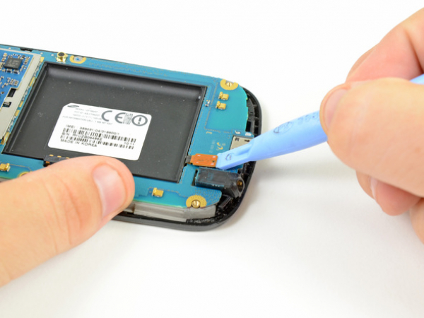


Step 12
Insert the flat edge of a plastic opening tool underneath the headphone jack connector and pry upwards.
Make sure to pry on the connector and not the socket itself, as prying the socket may cause serious damage.
Repeat the procedure for the digitizer and rear camera/SIM board connectors.