


Samsung Galaxy S5 MicroUSB Port Daughterboard Replacement

Send this link via e-mail
|
Tweet |
|


Step 1 - Front Panel Assembly (2)
If there's a piece of electrical tape covering the Wi-Fi antenna, speaker cable and the home button ribbon cable, remove it.


Step 3
Pull the home button ribbon cable out of its socket on the logic board. Do this with a pair of tweezers.
Step 5
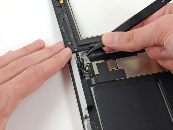
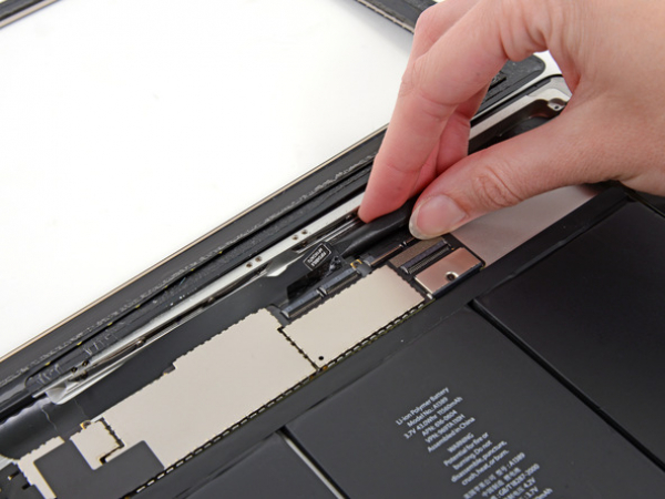
A piece of tape is securing the digitizer ribbon cable to the logic board. Peel it back with a pair of tweezers.


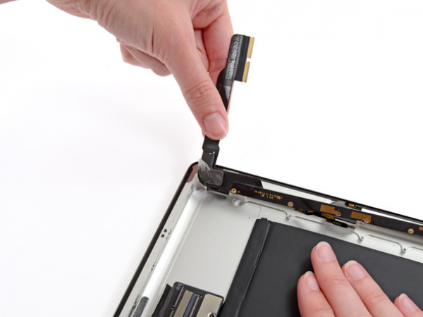
Step 7
Loosen the adhesive under the digitizer ribbon cable with the flat end of a spudger.
Take out the digitizer ribbon cable out of its sockets on the logic board.


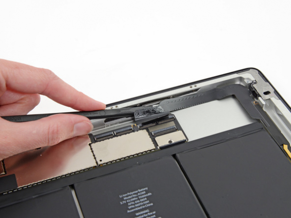
Step 8
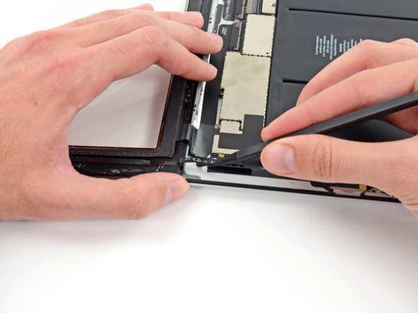
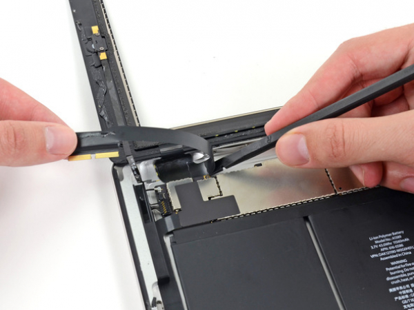
Peel back the digitizer ribbon cable. Separate the cable from the adhesive securing it to the rear aluminum case with the flat end of a spudger.
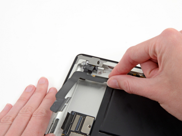
Step 9
Take the digitizer ribbon cable out of its niche in the aluminum frame. Do this with your fingers.
Separate the front panel from the iPad.


Step 10 - Headphone Jack Cable
Back to top
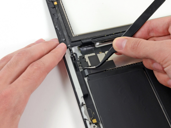
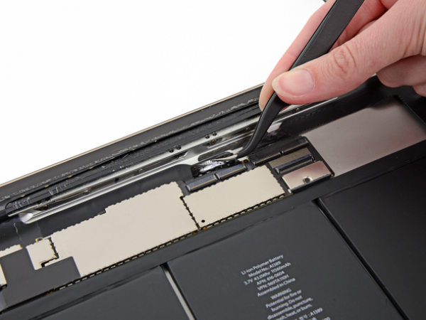
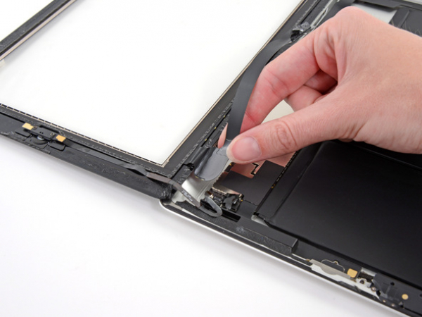
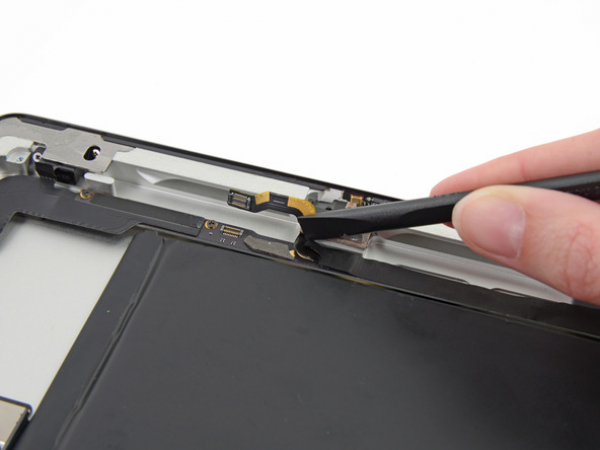
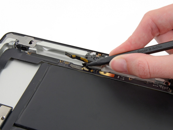
There's a piece of electrical tape covering the headphone jack assembly cable connector. Use tweezers to peel back the tape and remove it.
With the tip of a spudger, lift up the retaining flap on both ZIF connectors securing the headphone jack cable to the logic board.


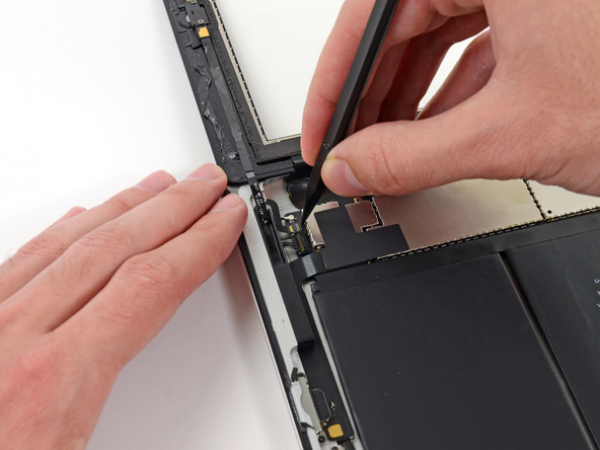
Step 11
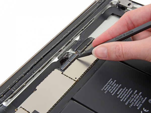
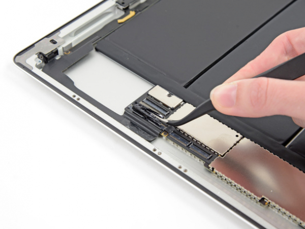
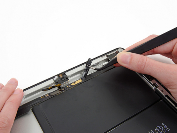
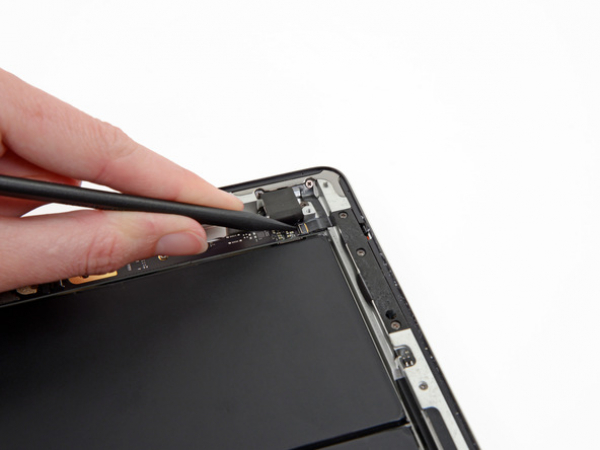
Push the flat end of a spudger underneath the headphone jack assembly cable and release the adhesive that's securing it to the rear aluminum frame.
Take the headphone jack assembly cable out of its socket on the logic board.
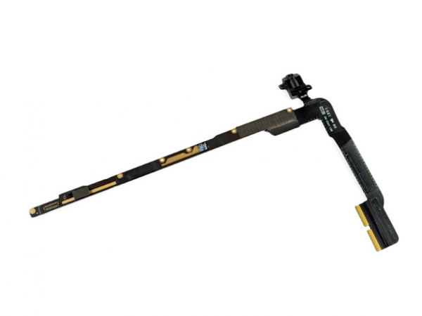
Step 12 - Headphone Jack Assembly
Back to top
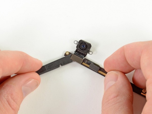
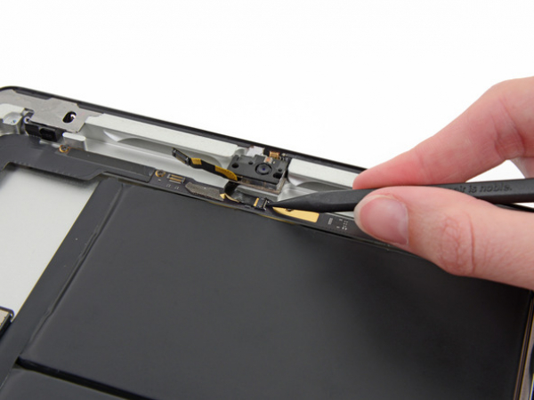
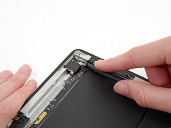
Move the front-facing camera ribbon cable aside using the flat edge of a spudger. Do NOT remove it.


Step 13
There's an adhesive tape covering covering the headphone jack assembly. Peel it back and remove it.


Step 15
Insert the tip of the spudger under the microphone ribbon cable. Gently push the cable out of its socket on the ZIF connector.
Move the microphone ribbon cable to the side with the flat edge of the spudger.
Step 16
A retaining flap is securing the volume/power button ribbon cable connector to the headphone jack assembly board. Flip it up.


Step 17
Move the volume button ribbon cable away from the ZIF connector.
Carefully bend the volume button ribbon cable upwards in order to move it aside.


Step 18
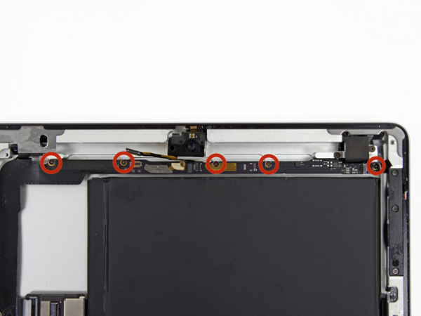
There are nine screws on the headphone jack assembly. You need to remove them.
Five 2.6 mm Phillips screws
Two 2.2 mm Phillips screws (Wide Head)
Two 2.6 mm Phillips screws
Make sure to hold the screwdriver in line with the screw, because the screws are angled into the aluminum frame and could be stripped easily.
Step 19
Hold the ribbon cable of the headphone jack assembly. Gently pull the assembly up and towards the top of the device.


Step 20
Pull the assembly from the iPad while holding the headphone jack assembly with your other hand. Make sure that the cables don't get caught.